How Fire Hydrant Systems Work
An end-to-end walk-through — from the underground tank to the landing valve on your 14th-floor corridor — of the components, codes and pressures behind a working fire hydrant network.
Last reviewed 7 May 2026 · 9 min read
Fire extinguishers are first-aid. A fire hydrant system is structural defence — engineered to deliver hundreds of litres of water per minute, on demand, to any point in a building. For commercial structures above 15 m, institutional buildings above 9 m, and most industrial premises, it is a statutory requirement under NBC 2016 Part 4 and codified in IS 13039:1991 (External Hydrant System) and IS 3844:1989 (Wet Riser System). This article unpacks every layer — from the underground tank to the topmost landing valve — with the actual codes, pressures and capacities that govern compliant design.
The four functional layers
A fire hydrant network is a sequence of four engineered layers. Get one wrong and the whole system underperforms when it's needed:
- Storage — a dedicated fire-water reservoir, typically an underground sump.
- Pressurisation — a pump room that takes water to design pressure on demand.
- Distribution — wet-riser pipework lifting water through the building plus an external yard loop.
- Delivery — landing valves and hose reels at every floor or zone, plus an external fire-brigade connection.
1. The underground water tank
The tank stores the fire-water reserve. Its minimum capacity is fixed by NBC Annex E2 according to building hazard:
| Building / Hazard class | Minimum capacity |
|---|---|
| Residential ≤ 15 m height | 20,000 L |
| Commercial / educational up to 30 m | 75,000 L |
| Commercial > 30 m or assembly buildings | 1,50,000 L |
| Industrial — moderate hazard | 2,00,000 L (min) |
| Industrial — high hazard (paint, solvent, hydrocarbon) | 3,00,000 L+ |
The tank itself must satisfy several rules:
- Construction: RCC or bolted-panel modular SS with sealed cover. Plastic tanks per IS 4985 are not permitted for fire-water reserve.
- Reserve protection: the fire-water portion is "ring-fenced" — the suction inlet for domestic / flushing water sits at a higher level, ensuring fire reserve cannot be drawn down for non-emergency use.
- Float valve: automatically tops up from the municipal main; a dual-level alarm signals stuck-open or stuck-closed.
- Inspection cover: low-level access for sediment removal and tank cleaning every 5 years.
- Anti-vortex plate on the suction header to prevent air entrainment when the pumps draw at peak flow.
2. The pump room — three pumps in coordination
Three pumps work as a coordinated team, each with a specific job:
- Jockey pump — small (typically 180 LPM at 7 bar). Maintains static pressure in the riser. Cycles ON/OFF on tiny leaks at threaded joints, valve glands and natural water-column shrinkage. A healthy jockey starts 4–8 times an hour; over 12/hour signals significant leakage.
- Main electric pump — high-capacity (typically 2,280 LPM at 7 bar for a Hazard Class B building). Cuts in automatically when pressure drops below the set threshold (usually 5.5 bar) caused by a hydrant valve being opened.
- Diesel standby pump — equal capacity. Auto-starts on three triggers: (a) electric pump failure to deliver pressure within 10 seconds, (b) mains power failure, (c) main pump motor over-current.
The pumps share a suction header and discharge into the same riser through non-return valves. The pump-room control panel monitors pressures, runs an automatic weekly test cycle and logs every start/stop. A trained engineer reviews the panel every quarter as part of an AMC.
Sizing the main pump (the math)
Per IS 13039, design flow is calculated by adding the simultaneous demand of the worst-case scenario:
- 2 hydrant valves @ 900 LPM each = 1,800 LPM
- 1 hose reel @ ~36 LPM
- 1 sprinkler zone (if applicable) @ ~450 LPM for ordinary hazard
Total typical demand: 2,280 LPM (without sprinklers) or up to 4,500 LPM (with sprinklers). Pump head is calculated as: static head + friction loss + residual pressure (3.5 bar) at most-remote outlet. For a 30 m building this typically lands around 70 m head — about 7 bar at the pump discharge, dropping to 3.5 bar at the topmost hydrant.
3. The wet riser, yard loop and pipework
From the pump-room, a steel main rises vertically through the building (the "wet riser") with branches at every floor. Specifications:
- Pipe material: medium or heavy class galvanised steel per BS 1387:1985 / IS 1239 part 1; flanged or welded joints, threaded only on small bores.
- Pipe size: 150 mm for buildings above 24 m or with sprinklers; 100 mm for shorter buildings.
- Pressure rating: Class C — rated for 14 bar working pressure. Hydrostatic tested at 1.5× working pressure (≈ 21 bar) before commissioning.
- Painting: red enamel finish (IS 5:2007 colour 537) over a zinc-rich primer; UV stable for outdoor sections.
- Air-release valves at the top of every vertical riser to expel air pockets that would otherwise prevent priming.
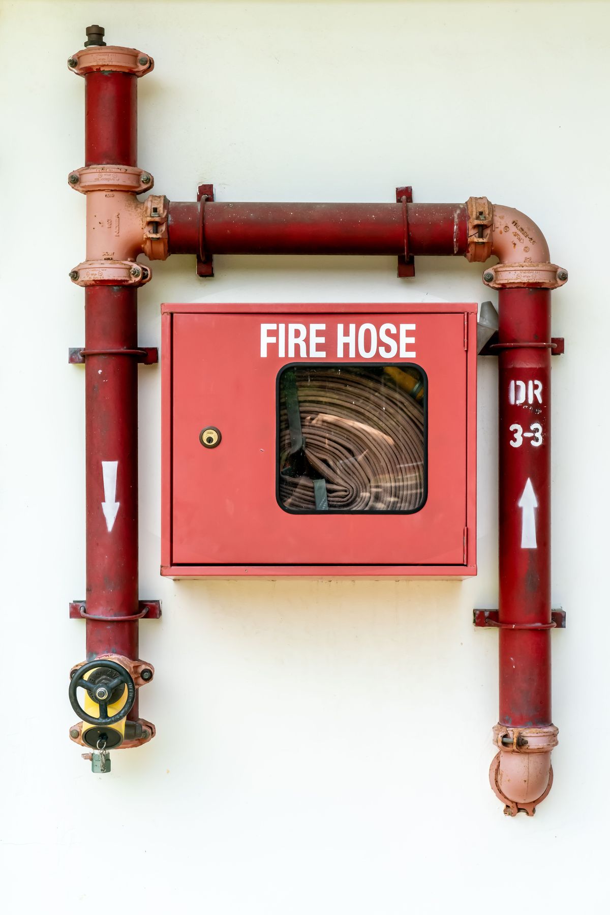
Outside the building, a yard hydrant loop runs around the periphery — typically 100 mm GI, with hydrant pillars every 30 m so a 30 m hose from any pillar reaches every external face. Each pillar carries a single or double gun-metal landing valve (IS 5290:1994) 750 mm above ground level.
4. Landing valves & hose-reel cabinets
At every floor, the riser terminates in a landing valve (also called a hydrant valve) — a single or double-headed gun-metal valve to IS 5290 with 63 mm instantaneous outlets, mounted in a glass-fronted hose cabinet. Beside (or within) it is the hose-reel cabinet containing:
- 15 m or 30 m of RRL hose pipe (Reinforced Rubber Lined, IS 636 Type-A or Type-B).
- Instantaneous couplings at each end (IS 903:1993, gun-metal, 63 mm).
- A branch pipe / spray-jet nozzle in aluminium or gun-metal (IS 903), giving both fog and jet pattern.
- A hydrant key for opening the valve under pressure.
The hose-reel is a faster-deploy first-response variant — a 20–30 m rubber hose on a swing reel any trained occupant can deploy without waiting for the fire brigade. It runs at lower pressure and lower flow than the main hydrant but is operable by a single person.
5. The fire-brigade connection
Mounted on the building façade at ground level, the fire-brigade connection (FBC) is a 2-way or 4-way manifold of female instantaneous inlets that the municipal fire brigade plugs into to either: (a) pressurise the building's hydrant system from their tender if the on-site pumps fail; or (b) directly draw water from the tank for their own appliances. Per IS 13039, the FBC is mandatory for every wet-riser installation. It's painted red, signed clearly, and located within 18 m of the road and 6 m from any wall.
Working pressures and design points
| Location | Static pressure | Running pressure (full flow) |
|---|---|---|
| Pump discharge (jockey-maintained) | 7.0 bar | 7.0–7.5 bar |
| Topmost / most-distant hydrant valve | ≥ 5.0 bar | ≥ 3.5 bar |
| Hose-reel nozzle | ≥ 2.0 bar | ≥ 2.0 bar |
| Maximum allowable static at any point | 8.0 bar (above this, install pressure-reducing valves) | |
How you know the system actually works — the test schedule
A hydrant system you don't test is a hydrant system you don't have. The IS-mandated schedule:
- Weekly pump trial — auto-start each pump for at least 5 minutes; record discharge pressure and any abnormal noise / vibration; verify diesel battery voltage ≥ 12.4 V.
- Monthly hydrant valve test — open one landing valve at the topmost / most-remote level; verify flow direction and visual pressure on a calibrated gauge.
- Quarterly hose unrolling — physically unroll every hose, inspect for cracks / coupling damage, re-roll on alternate face.
- Annual flow test — full hydraulic test at the most hydraulically-remote point; record actual LPM with a pitot gauge and bar pressure; the result must match the design point within 10%.
- 5-year hydrostatic test on the riser at 1.5× working pressure — required after any major modification or every 5 years.
All five are part of a properly-run AMC, and the records are the first thing fire-NOC inspectors ask to see. We cover the surrounding monthly self-checks in our monthly office fire safety checklist.
The hydrant system you don't test is the hydrant system you don't have.
Common failure modes (in order of frequency)
- Jockey pump cycling every minute — a leak is bleeding pressure faster than the system can hold. Cause: failed valve gland or a small underground pipe leak.
- Diesel pump won't start on demand — fuel old (degraded after 12 months in unstabilised tanks), battery flat, or the auto-start contactor seized from disuse.
- Landing valve gland leaks — minor but cumulative; signals overdue maintenance and triggers refill on the underground tank.
- Hose pipe binding from age — couplings won't seat properly under pressure; rubber liner cracks at the folds.
- Underground tank under-filled because of a stuck float valve and no level alarm.
- Sprinkler-zone control valve closed after a contractor's work and never re-opened — invisible at the panel because there's no tamper switch.
Cost & timeline for a new install
For a mid-sized commercial building (10,000–30,000 sq ft, 4–8 floors), a complete hydrant system — tank, pump room, riser, valves, hose reels, fire-brigade connection — typically requires:
- Design phase: 2–3 weeks (hydraulic calculation, BOQ, drawing approval)
- Material procurement: 4–6 weeks (pipes, pumps, valves all carry lead time)
- Installation: 4–8 weeks (civil prep, pipe routing, pump-room set-up, painting)
- Commissioning & testing: 1–2 weeks (hydrostatic, flow test, paperwork)
Capital cost varies dramatically with building height, hazard class and material grade. Range: ₹15–60 lakh for the building scale described, plus a recurring AMC of ₹50,000 – ₹2,00,000 / year. Send us your floor plan for a hydraulic-calc-backed written estimate, and we'll size the pumps and BOQ for your specific occupancy.
Looking after it long-term
Once installed, the single most important practice is consistent quarterly AMC visits with documented test records. Small problems caught early are inexpensive to fix; the same problems caught during a fire are expensive in ways that don't fit on an invoice. Read more on the operational layer in why AMC is critical for fire safety equipment.